
10‑48 inch LED LCD TV Light Strap Backlight Driver Board DIY Kit 11‑30V Input
la livraison GRATUITE
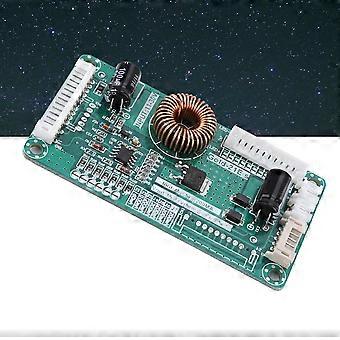
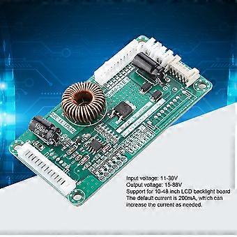
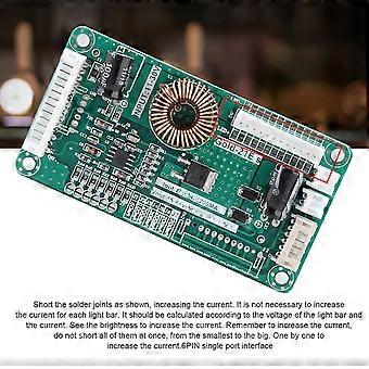
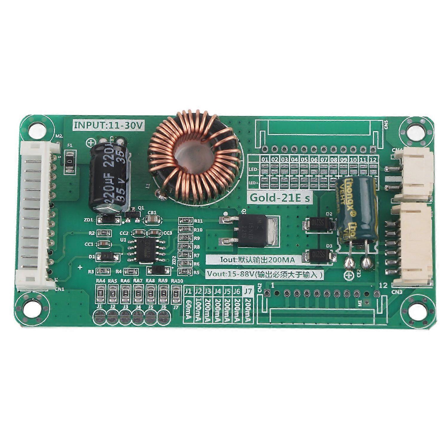
10‑48 inch LED LCD TV Light Strap Backlight Driver Board DIY Kit 11‑30V Input
- Marque: Unbranded
10‑48 inch LED LCD TV Light Strap Backlight Driver Board DIY Kit 11‑30V Input
- Marque: Unbranded
Économisez 3,00 € (20%)
Prix de vente recommandé
Économisez 3,00 € (20%)
Prix de vente recommandé
Nous acceptons les modes de paiement suivants
Description
10‑48 inch LED LCD TV Light Strap Backlight Driver Board DIY Kit 11‑30V Input
- Marque: Unbranded
- Catégorie: Circuits imprimés pour TV
- Identifiant Fruugo: 440685900-924800557
- EAN: 7409249041363
Livraison & retours
Expédition dans un délai de 2 jours
-
STANDARD: GRATUIT - Livraison entre lun. 22 décembre 2025–ven. 26 décembre 2025 - GRATUIT
Expédition de Chine.
Nous mettons tout en œuvre pour que les produits que vous commandez vous soient livrés dans leur intégralité et selon vos indications. Néanmoins, si vous recevez une commande incomplète, des articles différents de ceux commandés ou si, pour toute autre raison, la commande ne vous satisfait pas, vous pouvez retourner la commande ou tout produit inclus dans celle-ci et recevoir un remboursement complet des articles. Voir l'intégralité de la politique de retour
Détails de conformité du produit
Veuillez consulter les informations de conformité spécifiques à ce produit décrites ci-dessous.
Les informations suivantes sont fournies par le détaillant tiers indépendant vendant ce produit.
Fabricant:
Les informations suivantes indiquent les coordonnées du fabricant du produit concerné vendu sur Fruugo.
- Shenzhen Loma Li Technology Co., Ltd.
- Shenzhen Loma Li Technology Co., Ltd.
- nanwan jiedao xialilang shequ pingji dadao 1 hao jiansheng dasha A1215
- Longgang
- Shenzhen
- CN
- 518115
- gnng1213@163.com
- 18664926702
- https://hengruigongju.1688.com/page/index.html?spm=0.0.wp_pc_common_header_companyName_undefined.0
Personne responsable dans l'UE:
Les informations suivantes indiquent les coordonnées de la personne responsable dans l'UE. La personne responsable est l'opérateur économique désigné basé dans l'UE qui est responsable des obligations de conformité relatives au produit concerné vendu dans l'Union européenne.
- None
- Kequ Technology s.r.o.
- Pražákova 1008/69
- Štýřice
- Jihomoravský kraj
- Brno
- CZ
- 63900
- christopher25106@outlook.com
- 420608214795
- https://www.ozon.ru/seller/docool-583119/products/?miniapp=seller_583119